Industrial Machinery Company

Why Fuel Pump Commutators Fail and How to Fix Them?

A failing fuel pump can leave a vehicle silent at the worst possible moment. Sometimes, the warning begins with a weak hum, slow starting, or brief hesitation under load. Inside the motor, the Fuel Pump And Commutator assembly transfers electrical current through rotating copper segments. Brush contact keeps the pump running, but that contact gradually changes with heat, vibration, and wear.

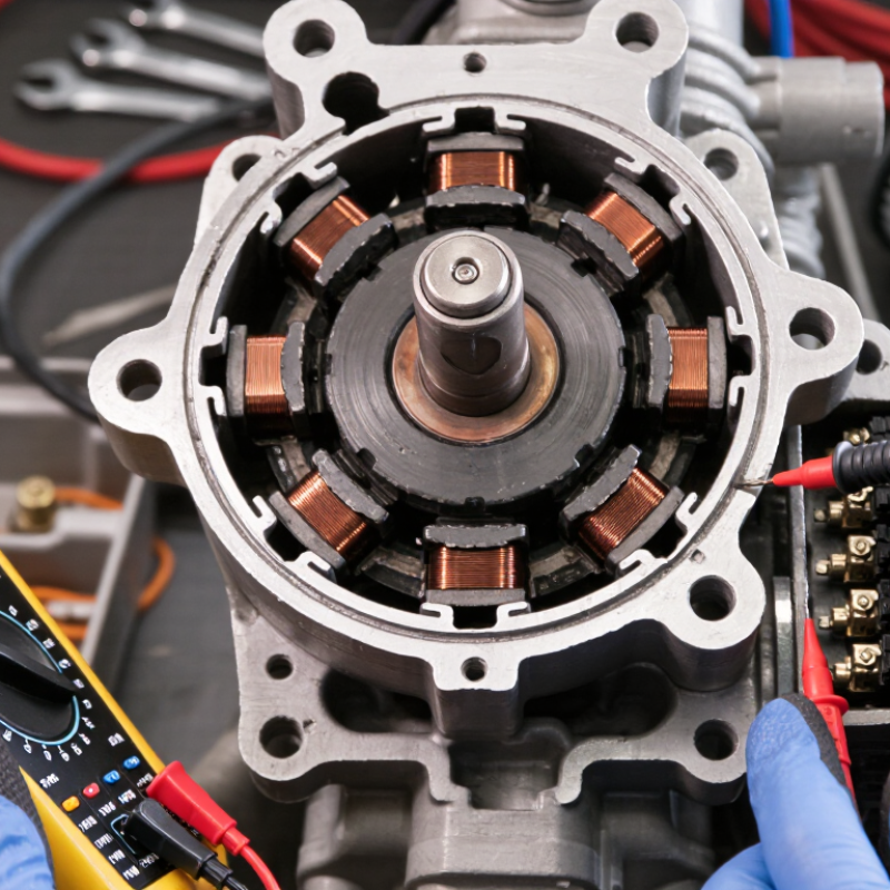
Commutator failure often appears as burned bars, deep grooves, uneven coloring, or heavy carbon dust. Small sparks may occur when brushes lose consistent contact. Excessive resistance can then reduce pump speed and fuel pressure. Low system voltage, contaminated fuel, restricted filters, and poor electrical connections can increase this stress. A technician should confirm pressure, voltage, current draw, and ground quality before blaming the commutator. Guessing wastes time.

The repair decision requires practical judgment. Some pumps allow motor servicing, while many modern modules are designed for complete replacement. Opening a fuel system without proper ventilation, approved tools, and manufacturer procedures creates avoidable danger. Use service data, insulated test equipment, and verified replacement parts. Do not rely on sound alone.

A useful inspection records the pump’s noise, pressure stability, connector condition, and current pattern. Heat marks around the terminals deserve attention. So do intermittent faults.

Even experienced technicians can misread a worn commutator as a simple relay problem. That possibility deserves reflection. A careful diagnosis separates brush wear from wiring faults, blocked filters, and failing regulators. This article explains why commutators fail, how symptoms develop, and which repair path offers dependable performance without replacing parts blindly.

Why Fuel Pump Commutators Fail and How to Fix Them?

Fuel Pump Commutators Explained: Copper Segments in 12–14.4 V DC Systems

Why Fuel Pump Commutators Fail and How to Fix Them?

A fuel pump commutator is more than a rotating contact. It contains copper segments that transfer current to the armature through carbon brushes. In a 12–14.4 V DC system, these segments switch current rapidly while the motor spins. Each segment must remain smooth, insulated, and evenly spaced. Small defects can create visible arcing, unstable pump speed, and reduced fuel delivery.

Heat, brush dust, low voltage, and contaminated fuel pump interiors can accelerate wear. A grooved copper surface may catch the brush edge. Pitted segments can increase electrical resistance. The pump may sound rough. It may also draw higher current than normal. Field technicians should measure voltage at the pump terminals, then compare current draw with the service specification. Voltage alone can mislead.

The diagnosis is not always clean. A dark commutator does not automatically mean failure. Mild discoloration may be normal, while raised copper edges require closer inspection. Disconnect power before testing. Use a magnifier to check for burned segments, loose connections, or uneven wear. Lightly cleaning a serviceable commutator may help, but aggressive sanding can remove critical copper thickness. Do not bridge the insulating gaps between segments. If segments are cracked, badly worn, or electrically open, replacing the motor or complete pump module is usually more reliable than repairing the commutator. Recheck terminal voltage under load. A weak connector or damaged ground can imitate commutator failure.

Why Fuel Pump Commutators Fail and How to Fix Them

Copper segments in 12–14.4 V DC fuel-pump motors increase in electrical resistance as they heat, raising voltage drop and I²R losses at the brush–commutator interface.

How to reduce failure: keep the commutator surface clean and smooth, replace worn or weak brushes, verify spring pressure, minimize connector resistance, and prevent fuel-pump overloading. Values are calculated from the standard copper temperature coefficient of resistance, α ≈ 0.00393/°C, normalized to copper resistance at 20°C.

Why Commutators Fail: Brush Wear, Arcing, Heat, and Fuel Contamination

Fuel-pump commutators fail through a chain of small electrical and mechanical stresses. Carbon brushes gradually wear, shortening their contact surface and increasing resistance. That resistance creates arcing between the brush and copper segments. The spark leaves tiny pits, dark carbon tracks, and uneven commutator surfaces.

Heat accelerates the damage. ISO 16750-4 environmental testing covers automotive temperature exposure from about -40°C to 150°C, depending on component location. Inside a fuel tank, poor cooling, restricted flow, or continuous low-fuel driving can push a motor toward its thermal limit. ASTM D4814 controls gasoline volatility and distillation properties, but it does not guarantee clean fuel. Dust, rust, water, or varnish can still enter the pump. Contamination acts like abrasive paste.

The evidence is often visible.

I inspect brush length, spring pressure, copper discoloration, and segment grooves. A 2023 automotive durability review published through SAE technical literature linked commutator wear mainly with current density, temperature, and contamination rather than mileage alone. That matters. A low-mileage pump can fail early under severe conditions.

Light polishing may remove superficial carbon. Deep pitting usually requires motor replacement, not aggressive sanding. The tank and electrical connector also need inspection. A repaired commutator can fail again if contamination remains. I have sometimes blamed the pump too quickly; voltage drop, poor grounding, and fuel restriction can create similar symptoms. Reliable diagnosis needs current measurement, pressure testing, and visual inspection under controlled conditions.

Why Fuel Pump Commutators Fail and How to Fix Them: Brush Wear, Arcing, Heat, and Fuel Contamination
Failure Cause Typical Physical Condition Common Symptoms Recommended Diagnostic Checks Corrective Action Prevention Risk Level
Brush Wear Carbon brushes become shorter, uneven, chipped, or unable to maintain sufficient spring pressure against the commutator. Intermittent pump operation, hard starting, reduced fuel delivery, increased electrical resistance, or complete pump failure. Inspect brush length and spring force where service access is available. Check for excessive voltage drop across the motor circuit and compare pump current with the vehicle service specification. Replace the brush assembly or the complete pump motor module if the brush holder, springs, or commutator are also damaged. Do not reuse weak brush springs. Maintain clean fuel, prevent repeated dry-running, and correct electrical supply problems that can increase motor load. High
Commutator Surface Wear Copper segments become grooved, discolored, uneven, or excessively polished. Mica insulation may become proud of the copper surface. Unstable current draw, reduced motor speed, electrical noise, intermittent operation, and visible sparking at the brush contact area. Inspect the commutator for grooves, raised mica, burned segments, loose segments, and an out-of-round surface. Check continuity between adjacent segments and confirm there is no short to the armature core. Lightly recondition a serviceable commutator only when permitted by the repair procedure. Replace the motor or pump module if segments are loose, deeply burned, cracked, or severely out of round. Prevent abrasive contamination, excessive brush pressure, overload, and prolonged operation with restricted fuel flow. High
Electrical Arcing Visible blue or yellow sparks, pitted copper segments, carbon deposits, and localized burning at the brush-to-commutator interface. Radio-frequency interference, fluctuating pump speed, blown fuses, elevated current draw, and rapid deterioration of brushes and commutator segments. Inspect brush contact, commutator cleanliness, brush seating, terminal connections, and armature continuity. Check for an open or shorted armature coil and excessive mechanical drag. Replace damaged brushes or the motor assembly. Repair loose terminals and eliminate the underlying overload or mechanical resistance. Do not continue operating a pump with severe arcing. Use correct electrical connections, maintain proper fuel flow, and replace components showing heat damage or poor brush contact. High
Excessive Heat Discolored copper, hardened or cracked brush material, melted insulation, heat-darkened terminals, or a distorted plastic carrier. Shortened service life, intermittent operation after warm-up, increased current draw, loss of fuel pressure, or shutdown followed by temporary recovery after cooling. Measure operating current, voltage at the pump terminals, fuel pressure, and voltage drop in the power and ground circuits. Inspect for restricted filters, blocked lines, poor cooling, and high bearing friction. Correct the cause of overload or poor electrical supply. Replace heat-damaged motor components, terminals, wiring, filters, or the complete pump module as required. Keep the tank adequately filled for submerged pump cooling, replace restricted filters, and ensure connectors and grounds are clean and tight. High
Fuel Contamination Rust particles, dirt, water, varnish, sediment, or degraded fuel deposits are found around the inlet screen, brushes, commutator, or pump rotor. Noisy operation, reduced fuel flow, pressure loss, rapid brush wear, sticking components, and recurring pump failure after replacement. Inspect the fuel tank, inlet strainer, fuel filter, and removed fuel sample. Look for abrasive particles, water separation, corrosion, and deposits on the pump internals. Drain and clean the tank when contamination is confirmed. Replace the filter and inlet strainer, flush affected lines, and replace the contaminated pump if internal wear is present. Use clean fuel from a reliable source, replace filters at the prescribed interval, and keep the fuel system sealed against water and debris. High
Dry Running or Low Fuel Level The pump operates without adequate fuel surrounding the motor, reducing cooling and lubrication and increasing brush and commutator temperature. Whining noise, intermittent delivery, hot pump housing, rapid wear, and failure shortly after repeated low-fuel operation. Review operating history, check tank fuel level, inspect the inlet strainer, and test pump current and fuel pressure under normal fuel-level conditions. Replace a pump damaged by overheating or seizure. Repair any fuel-level, pickup, or tank-baffle problem that allows the pump inlet to uncover. Avoid repeated operation with a very low fuel level and correct fuel pickup problems promptly. Medium
Restricted Filter or Fuel Line The pump works against increased resistance because of a clogged filter, collapsed hose, blocked strainer, or contaminated line. High-pitched pump noise, low fuel pressure, poor acceleration, lean running, elevated current draw, and excessive motor temperature. Measure fuel pressure and flow before and after the filter where possible. Compare pump current and pressure with the applicable service specifications. Replace the restricted filter or hose, clean the strainer, and retest pressure, flow, voltage, and current. Replace the pump if it has suffered secondary damage. Follow the recommended filter replacement interval and investigate any sudden change in pump sound or fuel pressure. Medium
Poor Electrical Connections Loose, corroded, overheated, or undersized terminals create resistance in the pump power or ground circuit. Slow pump speed, hard starting, intermittent operation, hot connectors, voltage-related fault codes, and low fuel pressure. Perform a loaded voltage-drop test on both positive and ground circuits. Inspect terminals for discoloration, looseness, corrosion, and damaged crimp joints. Repair or replace damaged terminals, wiring, relays, fuses, and grounds. Retest voltage at the pump while it is operating under load. Protect connectors from moisture, use correct terminal repairs, and verify secure grounds during electrical service. Medium
Mechanical Drag or Bearing Wear Armature shaft, bushings, bearings, or pump gears show scoring, binding, excessive play, or contamination-related resistance. Growling or grinding noise, high current draw, slow acceleration of the motor, overheating, and repeated arcing. Check shaft rotation where accessible, listen for abnormal noise, measure operating current, and inspect for rotor-to-stator contact or damaged pump components. Replace worn bearings, bushings, or the complete pump assembly according to the service design. Remove contamination before installing a replacement. Keep abrasive debris and water out of the fuel system and address unusual pump noise before electrical damage develops. High
Incorrect Pump Application or Overload The motor operates outside its intended pressure, flow, voltage, or duty range, causing persistent high current and commutator stress. Repeated fuse failure, excessive noise, low delivery, rapid brush wear, overheating, and premature commutator damage. Verify the required system pressure and flow, operating voltage, fuse rating, regulator condition, and pump current against the vehicle or equipment specification. Install a correctly specified pump and repair restrictions, regulator faults, or wiring problems that create abnormal load. Match the pump to the required pressure and flow range and avoid using an undersized or incompatible replacement. High
Diagnostic note: Always compare voltage, current, fuel pressure, and flow with the applicable service specifications. Relieve fuel-system pressure before disconnecting fuel lines, work in a well-ventilated area, and keep ignition sources away from fuel vapors.

Diagnosing Faults Through Voltage-Drop and Pump Current Measurements

Why Fuel Pump Commutators Fail and How to Fix Them?

A failing fuel pump commutator often reveals itself through unstable current and intermittent pressure. Do not condemn the pump immediately. Measure voltage at the battery and at the pump connector while the engine runs or the circuit is loaded. The difference is voltage drop. A healthy circuit usually shows a small drop, but always compare the reading with the vehicle’s service specification. Excessive loss on the positive side suggests damaged wiring, weak terminals, or a failing relay.

Test the ground side separately. Place one meter lead on the pump ground terminal and the other on battery negative. A high reading indicates resistance in the ground path. Corroded connectors can feel tight but still restrict current. That detail is easy to miss.

Then measure pump current with a suitable clamp meter. High current may indicate worn bearings, restricted fuel flow, or a commutator dragging against damaged brushes. Low or fluctuating current can suggest open commutator segments, poor brush contact, or inadequate voltage supply. Watch the waveform if an oscilloscope is available. Repeating spikes often expose dead spots that a basic meter hides.

A practical repair may involve replacing the pump module, cleaning approved connections, or repairing the harness. Commutator resurfacing is rarely reliable inside a sealed automotive pump. The method is not perfect. Fuel temperature, tank level, and wiring length can change results, so record conditions before judging the measurement.

Repair Options: Cleaning, Resurfacing, Brush Replacement, or Pump Renewal

Why Fuel Pump Commutators Fail and How to Fix Them?

A fuel pump commutator transfers current through the brushes while the motor spins. Heat, carbon dust, moisture, and brush wear can damage its copper segments. Symptoms often include intermittent starting, weak fuel delivery, or a pump that stops after warming. Disconnect power before inspection, and work in a clean, well-ventilated area away from ignition sources.

Cleaning is suitable when the commutator has a light carbon film but no deep grooves. Use approved electrical cleaner and a lint-free cloth. Do not scrape the copper with a hard blade. One small mistake can widen the damage.

If the surface is uneven, careful resurfacing can restore brush contact. A technician should check segment runout, insulation depth, and the remaining commutator diameter afterward. Excessive sanding removes useful copper and may shorten the motor’s life.

Brush replacement makes sense when brushes are short, chipped, or sticking in their holders. New brushes must move freely and seat evenly against the commutator. A short bedding period may be needed. I have seen repairs fail because the brush springs were weak, not because the commutator was defective.

Pump renewal is safer when segments are burnt, loose, deeply pitted, or connected to a worn armature, noisy bearing, or damaged shaft. Repairing one part cannot reliably correct several worn components.

Post-Repair Testing Under ISO 16750-2 Electrical Stress Conditions

Why Fuel Pump Commutators Fail and How to Fix Them?

Fuel pump commutators usually fail through brush arcing, contamination, uneven wear, or excessive heat. A darkened commutator is not automatically defective. Deep grooves, raised bars, and burnt copper need closer inspection. Check brush spring pressure, armature resistance, and shaft runout before replacing parts. A clean repair can still hide poor electrical contact.

Post-repair testing should follow ISO 16750-2 electrical stress procedures. The standard covers voltage variations, supply interruptions, overvoltage, superimposed alternating voltage, and transient disturbances. Test the repaired pump during cold-start voltage dips, repeated switching, and stabilized running voltage. Record current draw, delivery pressure, noise, and commutator temperature. Small changes matter.

Use calibrated equipment and document each result. SAE J1455 also identifies electrical transients and environmental stresses relevant to vehicle components. Do not judge the repair from one successful bench run. A pump may pass at room temperature, then show arcing after heat soak. This is common enough to respect. In practice, I would repeat the test after vibration exposure, because loose brush seating can appear later. The weak point may be the repair process itself, not the new commutator. ISO 16750-2 test severity must match the vehicle installation, wiring length, protection circuit, and electrical architecture. A generic pass result is not sufficient evidence.