Industrial Machinery Company

How to Build a 555 IC Timer Circuit

A 555 Ic Timer Circuit can turn a handful of ordinary parts into a pulsing LED, a simple alarm, or a basic timing device. The first build is approachable, but small wiring errors can make the output stay high or stop oscillating. A breadboard, a low-voltage supply, one 555 timer, two resistors, and a capacitor are enough to explore the basics. Keep the supply within the limits of your specific timer chip.

Hans Camenzind, the engineer who designed the original 555, is often credited with calling it “probably the most successful integrated circuit ever made.” Its appeal is practical: the chip combines timing and switching functions in a compact package. This guide introduces an astable circuit, where the output repeatedly changes state. You will connect pins 2 and 6, choose resistor and capacitor values, and observe the output at pin 3. A small LED can make each pulse visible.

Details matter. Check the pin numbers against the package diagram before applying power. A reversed electrolytic capacitor or an overlooked reset pin can spoil an otherwise sound layout. Start with a slow blink, then adjust the component values and compare the result with your calculations. Real components vary, so the measured timing may not match perfectly. That is part of the lesson. The 555 IC Timer Circuit is simple, but not magic; careful wiring and patient testing make it dependable.
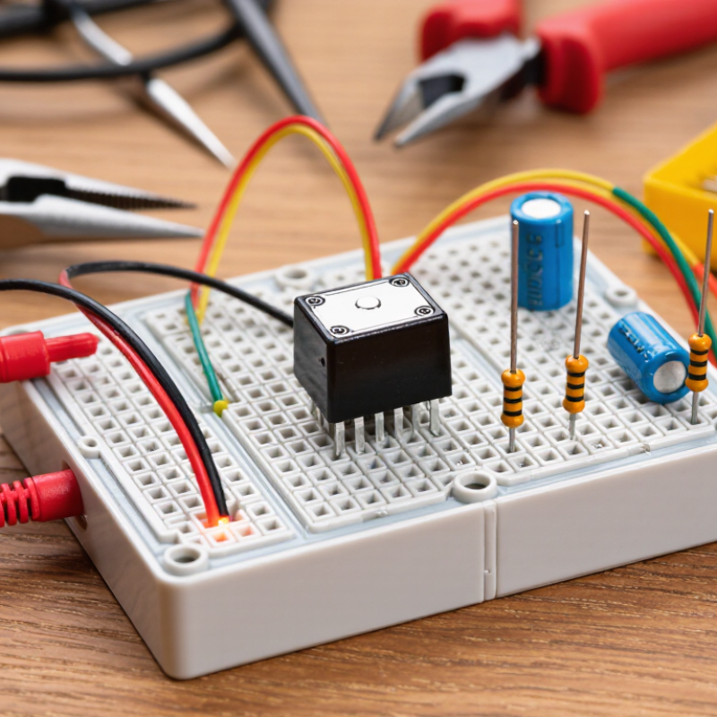
How to Build a 555 IC Timer Circuit

Understand the Operating Modes of a 555 Timer

The 555 timer has three common operating modes: monostable, astable, and bistable. Each mode uses the same internal comparators and latch, but connects the timing components differently.

In monostable mode, a brief trigger below one-third of the supply voltage sets the output high. A capacitor then charges through a resistor. When its voltage reaches about two-thirds of the supply, the output returns low. One trigger, one pulse. This mode suits simple delays or pulse stretching.

Astable mode repeatedly charges and discharges a capacitor, producing a continuous square wave. The resistors and capacitor set its approximate frequency and duty cycle.

In bistable mode, separate trigger and reset signals switch the output between two stable states. It can hold a state without a timing capacitor. That distinction matters.

On a breadboard, add a small bypass capacitor near the supply pins and check the output with a meter or oscilloscope. The neat equations can seem more exact than the circuit really is. Component tolerances and wiring affect timing, so measure your result before relying on it. A first build may not match the calculation perfectly. That is useful feedback, not necessarily a faulty timer.

Gather the Components and Tools

Before wiring a 555 timer, set out the IC, solderless breadboard, insulated jumper wires, resistors, a capacitor, an LED, and a regulated low-voltage supply. Add a digital multimeter and small side cutters; the meter helps catch reversed connections before power is applied. A bipolar 555’s published data sheets commonly specify a 4.5–16 V operating supply, but CMOS versions differ, so check the exact device’s data sheet before choosing a supply. Keep it simple. A 1 kΩ resistor and a 10 µF capacitor make a practical starting pair for a slow blink circuit, though the actual timing also depends on the circuit configuration and component tolerances.

Choose components with clearly printed values, and sort them into a shallow tray; tiny resistors disappear easily. A 5% resistor can vary from its marked value, so do not expect a perfectly exact blink rate. That part still catches me out. Use a breadboard with clean contacts, and keep the LED’s series resistor in place to limit current. For static-sensitive CMOS parts, follow the ESD handling guidance in IEC 61340-5-1, which covers protection of electronic devices and assemblies. A grounded work surface and careful handling reduce avoidable risk. Check the supply polarity, resistor values, and capacitor markings against the circuit diagram before switching on.

How to Build a 555 IC Timer Circuit: Gather the Components and Tools

A basic LED-flashing circuit typically uses one 555 timer IC, three resistors, two capacitors, one LED, a breadboard, and jumper wires. You will also need a wire cutter and a multimeter to assemble and check the circuit.

Choose the Circuit Configuration and Timing Values

For a 555 IC timer circuit, choose the configuration that matches the job. Use monostable mode when one input pulse should create one timed output. Its output duration is approximately 1.1 × R × C. For a delay near one second, a 100-kilohm resistor and a 10-microfarad capacitor are a practical starting point. Use astable mode for a repeating signal, such as a blinking LED. It needs no trigger pulse.

In astable mode, the approximate frequency is:

1.44 ÷ ((RA + 2RB) × C)

With RA at 10 kilohms, RB at 47 kilohms, and C at 10 microfarads, expect about 1.4 cycles per second. The output stays high for roughly 0.4 seconds and low for 0.3 seconds. These are estimates, not promises. Capacitor tolerance and leakage can shift the timing, especially with larger electrolytic capacitors. I’ve found it useful to measure the finished circuit rather than trust the calculation alone; that small step is easy to forget.

Tips: Place a 100-nanofarad bypass capacitor close to the timer’s supply pins. Keep the reset pin at a defined high level if unused. Test with the intended load connected, since a heavy load can affect the output. Start with conservative values, then adjust one component at a time.

Assemble the 555 Timer Circuit

Build the circuit on a solderless breadboard with the power disconnected. Place the 555 timer across the center gap, with its notch facing upward. Connect pin 1 to ground and pin 8 to a regulated 5–9 V supply. Join pin 4 to pin 8 to keep the timer enabled. Use a short jumper to connect pins 2 and 6. Add a 10 kΩ resistor from the supply to pin 7, then a 47 kΩ resistor from pin 7 to pins 2 and 6. Connect a 10 µF capacitor between pins 2 and 6, and ground; its negative lead goes to ground. These values should produce a visible blink, though timing varies slightly.

Connect pin 3 to a 1 kΩ resistor and LED in series, then return to ground. Point the LED’s flat edge toward ground. Add a 100 nF capacitor directly between pins 8 and 1 to reduce supply noise. A 10 nF capacitor from pin 5 to ground is optional. Keep the leads short. Before applying power, check the timer’s notch, capacitor polarity, and every jumper. If the LED stays dark, disconnect power and inspect the pin connections; a misplaced breadboard wire is easy to overlook. The first layout may look messy, and that is worth correcting before soldering.

How to Build a 555 IC Timer Circuit - Assemble the 555 Timer Circuit
Section Component or Connection Specification Assembly Notes
Circuit type 555 timer in astable mode Continuously repeating output pulse The output alternates between a high and low state while the timing capacitor charges and discharges.
Power supply DC supply 5–9 V for this example Connect the positive supply to pin 8 and the ground rail to pin 1. Check the timer IC’s datasheet for its permitted supply range.
Timer IC 8-pin 555 timer Standard 555 pin arrangement Identify pin 1 from the package’s notch or dot before wiring. Pin numbering proceeds counterclockwise when viewed from above.
Timing resistor RA Resistor between VCC and pin 7 10 kΩ Connect one end to pin 8 (VCC) and the other end to pin 7 (discharge).
Timing resistor RB Resistor between pin 7 and the timing node 68 kΩ Connect one end to pin 7 and the other end to the joined pins 2 and 6.
Timing capacitor Capacitor from the timing node to ground 10 µF Connect the positive lead to the joined pins 2 and 6 and the negative lead to ground. Observe polarity if using an electrolytic capacitor.
Trigger and threshold Pins 2 and 6 Connect together Join the trigger pin and threshold pin to the timing node shared by RB and the capacitor.
Reset Pin 4 Connect to VCC Holding reset low disables the timer; connect it to the positive supply for normal operation.
Control voltage Pin 5 to ground 10 nF (0.01 µF) ceramic capacitor Connect the capacitor between pin 5 and ground to help reduce unwanted triggering from electrical noise.
Output indicator Pin 3, current-limiting resistor, and LED 1 kΩ resistor in series with an LED For a simple indicator, connect pin 3 through the resistor to the LED anode, then connect the LED cathode to ground. The resistor limits LED current.
Supply decoupling Capacitor between pins 8 and 1 100 nF ceramic capacitor Place it close to the IC, with one lead on VCC and the other on ground, to help reduce supply-noise effects.
Expected timing Output period and frequency About 1.01 s per cycle; about 0.99 Hz Using the ideal formulas and the example values: frequency ≈ 1.44 ÷ ((RA + 2RB) × C). Actual timing varies with component tolerances and the specific timer IC.
Expected pulse times High time and low time About 0.54 s high; about 0.47 s low Ideal estimates: high time ≈ 0.693 × (RA + RB) × C; low time ≈ 0.693 × RB × C. The resulting duty cycle is about 53%.
Before powering on Wiring and polarity check Verify supply, pin connections, and capacitor polarity Confirm pins 2 and 6 are joined, pin 4 is high, and the timing capacitor and LED are oriented correctly. Avoid shorting the supply rails.

Test the Circuit and Troubleshoot Common Problems

With the 555 timer assembled, test it before placing it in a permanent enclosure. Set a current-limited bench supply to the circuit’s rated voltage, then connect it with power off. Start with the basics. Check that pin 1 reaches ground and pin 8 receives positive voltage. In a typical astable circuit, pins 2 and 6 connect together, while pin 4 stays high. A small LED and series resistor on pin 3 make the output easy to see. It should blink steadily. A multimeter set to voltage can confirm that pin 3 changes between low and high levels.

If the LED stays dark, disconnect power and inspect each wire against the circuit diagram. A loose breadboard jumper can look connected but sit one row away. Check the LED direction, resistor value, and electrolytic capacitor polarity; a reversed capacitor is an easy mistake. It is tempting to blame the timer, but wiring faults are often more likely. If the LED remains on, verify the timing capacitor and resistors, especially their connections to pins 2, 6, and 7. A blink rate that seems wrong may simply reflect component tolerances. I sometimes rush past that detail. Change one component at a time, then retest, so the cause of a change stays clear.